Motivation
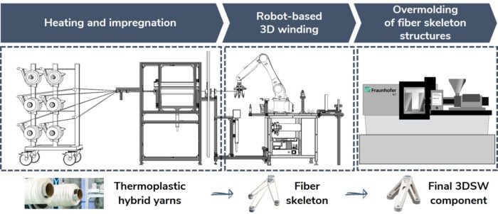
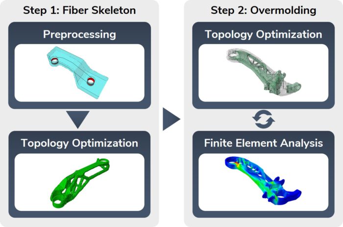
The 3D skeleton winding (3DSW) technology uses injection overmolded fiber skeletons. Based on this, the amount of expensive continuous fibers is reduced to a minimum by using load path-appropriate fiber skeletons. In combination with topology-optimized overmolding structure, cost-efficient lightweight structures are enabled.
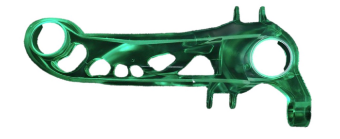
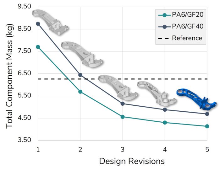
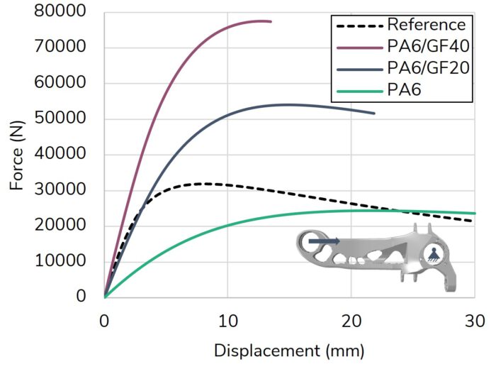
The Korean German ZIM project ACCORD focused on the industrialization of the 3DSW technology. The achievements include a fully automated and CE-certified winding cell as well as a virtual optimization and validation approach for 3DSW structures. Both were applied to design a 3DSW rear trailing arm for a Hyundai Santa Fe. Iterative virtual optimization and validation enabled a reduction of the component mass by up to 37 % compared to the metallic reference structure.