MACROSCOPIC DRAPING SIMULATION FOR NON-CRIMP FABRICS (NCF)

SimuDrape unlocks efficient and accurate draping simulation for NCF materials.
Check out the validation results for an aerospace application!

Motivation

Resin Transfer Molding (RTM) requires the draping of flat engineering textiles into the three-dimensional shape of the part. This processing step is accompanied by manufacturing effects, such as an altered fiber orientation or fiber volume content. Moreover, manufacturing defects, such as gapping or wrinkling might occur. Draping simulation is a powerful tool for predicting manufacturing effects and defects and thus optimize the draping process.

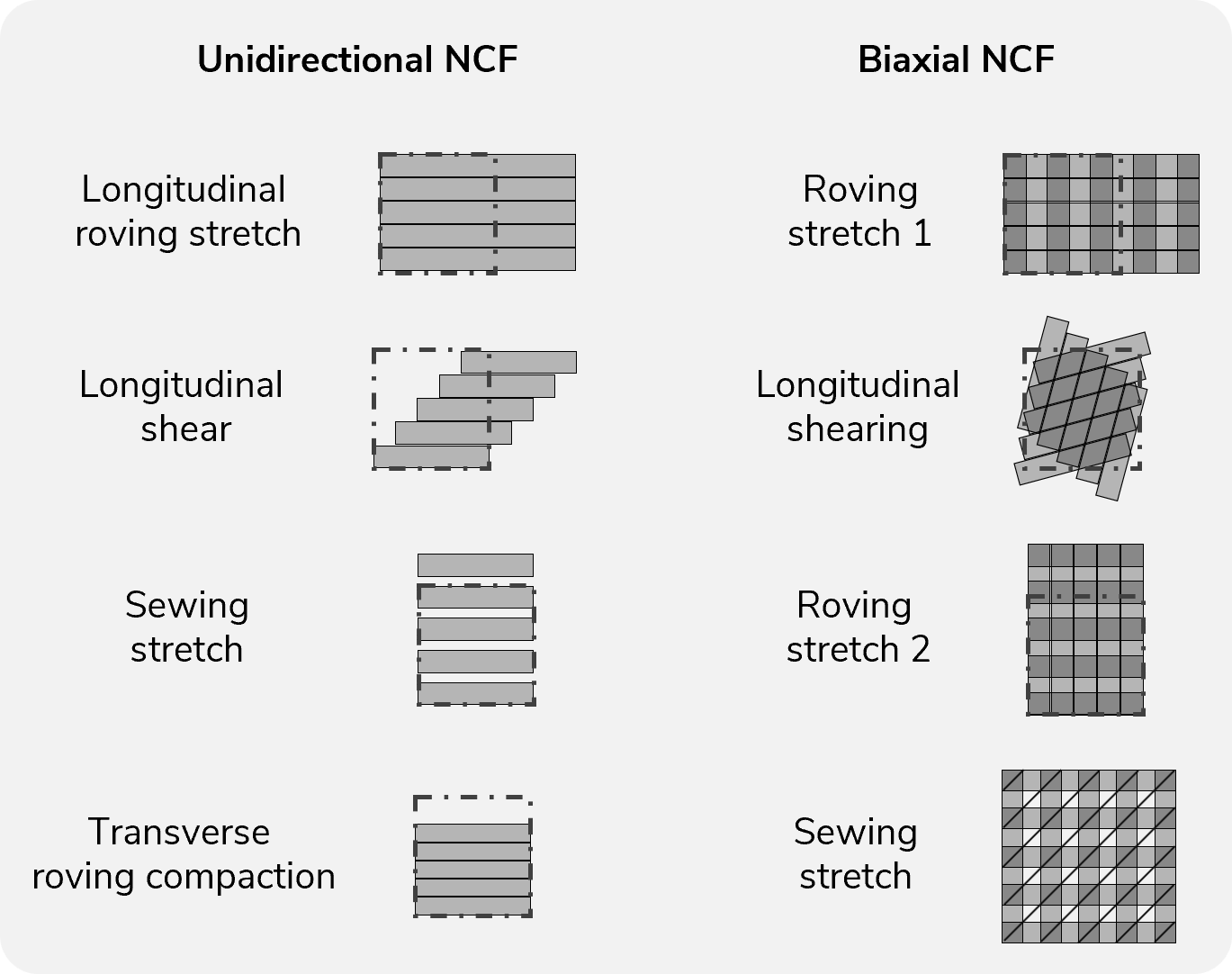
Modelling draping on the macroscopic level is essential for efficiently simulating industrial-scale components. While macroscopic models for woven fabrics are already state of the art, such methods have yet to be established for NCF. Most simulations of NCF have been conducted at the mesoscopic level, where the fibers and the stitching are captured discretely. More recently, NCF models have also been developed at the macroscopic level [1, 2].

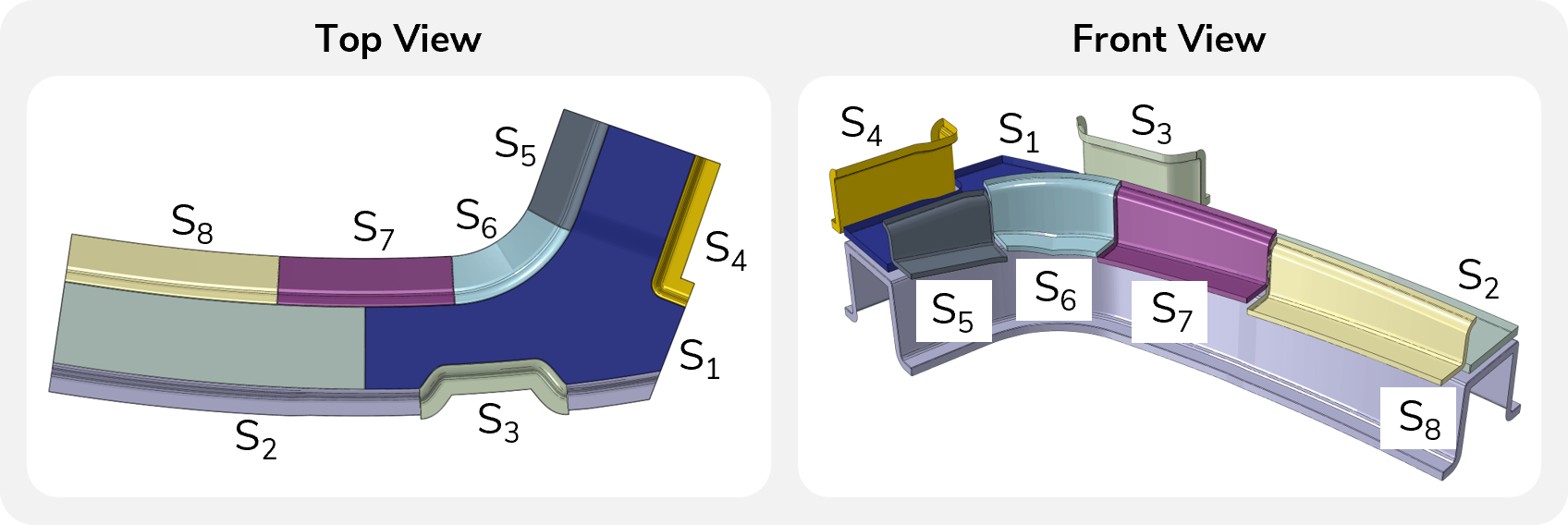
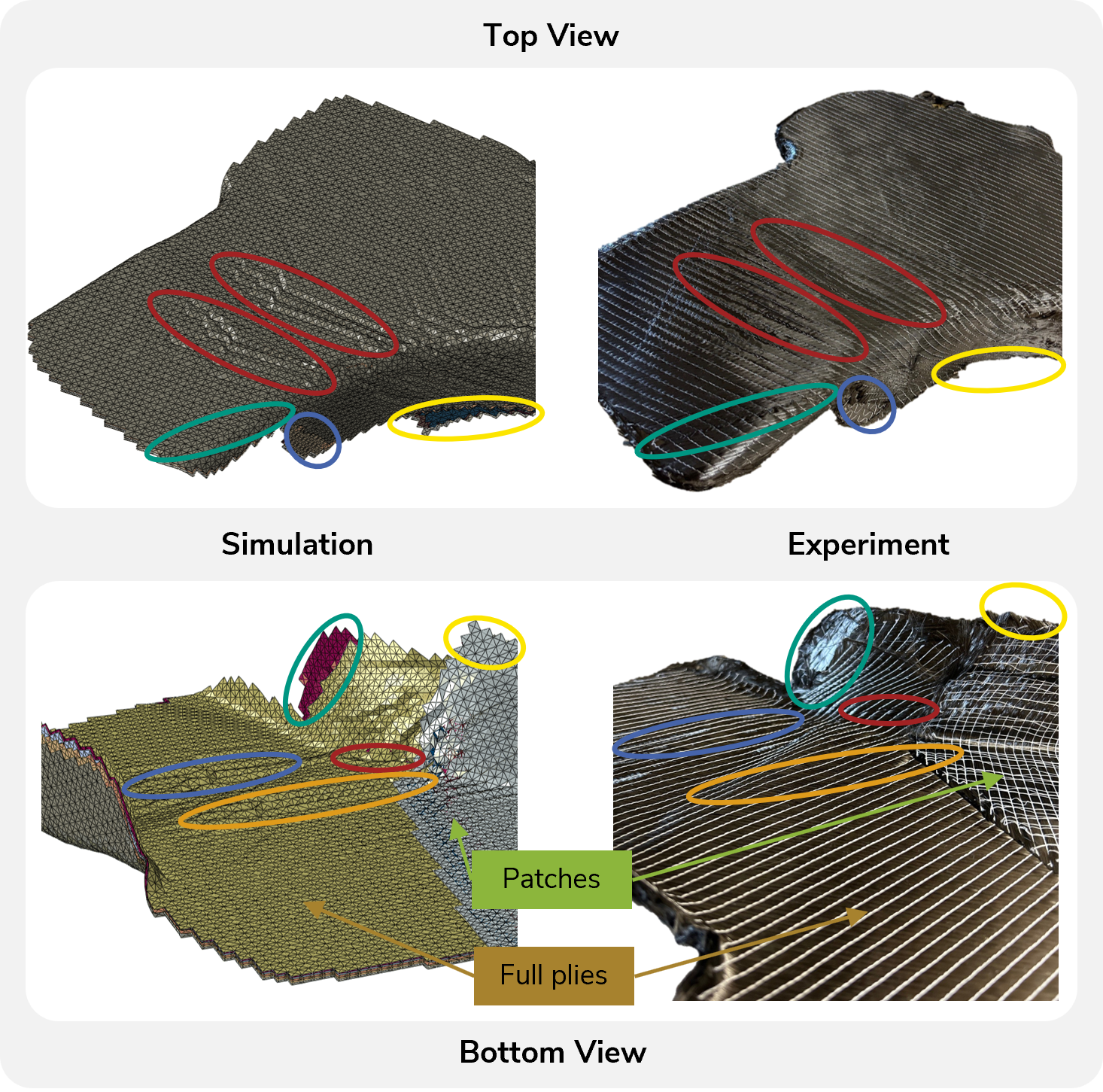
This macroscopic approach for NCF draping simulation has been adopted in the public-funded project ELECTRA and applied to a complexly shaped aerospace structure [3]. A high prediction accuracy for local wrinkling behavior is observed and the key outcomes are presented in the following.

Key takeaways

  • Macroscopic draping simulation is essential for draping simulation for industrial-scale components
  • A macroscopic modeling approach for non-crimp fabrics (NCF) has been developed by KIT-FAST and recently been made available in SimuDrape
  • High prediction accuracy for local wrinkling is observed for an aerospace component with a stack of UD and biaxial NCF

project partners

Material Modeling

Material modeling for draping simulation requires considering intra-ply (membrane, bending) and inter-ply mechanisms (tool-ply and ply-ply-friction). Bending and friction modeling can be adopted for NCF materials from existing modeling approaches, such as those available through SimuDrape. In contrast, membrane behavior requires a modeling approach tailored to NCF materials.

The macroscopic modeling approach developed by KIT-FAST [1, 2] follows hyperelastic material modeling and is based on so-called pseudo-invariants. Those pseudo-invariants capture the specific membrane deformation mechanisms for NCF materials. Accompanied by different types of nonlinear stress energy functions as well as coupling functions to couple different pseudo-invariants, the membrane deformation behavior of NCF materials can be captured.

This approach is implemented into Abaqus through a VUMAT subroutine and can describe the membrane behavior for unidirectional (UD) and biaxial NCF materials. Recently, this approach has been made available in SimuDrape.

Pseudo invariants to capture the membrane deformation for NCF materials.

Material Card Creation

Three NCF have been characterized, which includes a UD-NCF as well as a 0/90 and a +/-45 biaxial NCF. Bending and friction are characterized through cantilever tests and a sled-based testing rig, respectively. These tests are state-of-the-art and therefore not discussed further.

For membrane behavior, off-axis tension tests in different angles are adopted. 30°, 45°, and 60° are considered for the UD-NCF, which has proven to provide holistic characterization of longitudinal shear as well as transverse stretch and compression. In contrast, +45° and -45° are used for the biaxial NCF, since the deformation of biaxial NCF is driven by pure shear deformation. The different angles are used to capture potential asymmetries, as for instance introduced by the sewing of +/-45° NCFs.

The characterization results serve as the basis to inversely identify the parameters of the modeling approach through an FEA of the off-axis tensions tests. An overall good agreement is observed for all material variants, as exemplarily shown for the UD-NCF.

Parameterization result for a UD-NCF.

Draping Simulation Workflow

In this project, the geometry and laminate layup are a predefined boundary condition due to the targeted application. Thus, there was no opportunity to optimize the geometry upon the results from draping simulation.  

The laminate layup comprises 16 layers of UD and biaxial NCF and additional four patches for local reinforcement. The tight radius and the resulting double curvature make draping a challenging task that requires a customized and segmented stamp concept.  

The developed draping concept is used to mitigate the strike-out from inner to outer areas of hand-draping processes. Initially, the stamps in the flat area are used to fix the laminate layup. Subsequently, the moderately shaped areas at stamps 3 and 4 are draped. Finally, stamps 6 to 8 are used to smoothly drape the critical radius area.

Stamp concept for draping the aerospace structure.

Validation

The tooling concept was manufactured and the preforms draped following the outlined above. The experimental results are then compared qualitatively to the simulation results for validation of the draping simulation.

Comparing the top view in the red areas, wrinkles that extend almost over the entire width of the part form in both the simulation and the preform. In the green area, shear deformation is predicted. This shear deformation is due to rovings to the right of the green area, being not pulled over the edge into the radius, unlike the rovings on the left. The blue marking shows the material draw-in of the top layer, which is well predicted by simulation. The patch-plies located on the bottom of the layup emerge in simulation from underneath, see the yellow marking. This behavior is not observed in the experiment. This inaccurate prediction of ply-ply behavior is due to the assumption of simple Coulomb friction between the plies and the neglect of the binder behavior.

Comparing the bottom view, the material draw-in from the bottom is well predicted. In both the simulation and the experiment, wrinkles appear in the blue area. While wrinkles are predicted in the orange area in the simulation, they do not occur in the experiment. In the area marked in red, a severe wrinkle, which is completely folded over, can be seen in the simulation as well as experimental results.

In summary, the adopted approach yields a high prediction accuracy. Given the fact that this macroscopic draping delivers results efficiently, the approach is expected to be ready to be used for industrial-scale applications.

References

  1. Macroscopic forming simulation of unidirectional non-crimp fabrics: Hyperelastic material modeling and 3D-solid-shell approach. Doctoral thesis Schäfer, B. B. J., May 27, 2024. Karlsruhe Institute of Technology (KIT). doi:10.5445/IR/1000170739 
  2. A hyperelastic approach for modeling the membrane behavior in finite element forming simulation of unidirectional non-crimp fabrics (UD-NCF) Schäfer, B.; Dörr, D.; Zheng, R.; Naouar, N.; Kärger, L., 2024. Composites Part A: Applied Science and Manufacturing, 185, Art.-Nr.: 108359. doi:10.1016/j.compositesa.2024.108359 
  3. Prediction quality of macroscopic forming simulation of non-crimp fabrics for aerospace applications; Wank J.-P.; Haas, S.; Dörr, D.; Runeberg, P.; Lux, B.; Krauß, C.; Schäfer, B.; Kärger, L., 2025. ESAFORM 2025 Conference Proceedings. 
 

Any questions?

Do not hesitate to get in contact with us if you have any questions or if you are interested in a collaboration. We are pleased if you leave us a message!